


Western’s advanced Bridging Pit Depth Gauge System® and our new Jr. Bridging Pit Depth Gauge® take over, where the capabilities of our standard Pit Gauges fall short, for evaluating large areas of Weightloss Corrosion. These Bridging Bar type Pit Gauges can also be used to measure Dents and Buckles on Pipelines, Shell Settlement on Storage Tanks, etc. These various forms of Bridging Bars can utilize any of our exclusive Dial Indicators (Imperial, Metric, or Digital), with any of our Custom Engineered Contact Points. There are several important features to a Segmented Bridge, where various elements (Blades and Tee’s) are assembled to form a Bridging Bar. Firstly, they can be assembled to follow the contour of a slightly irregular surface. This contouring feature is important for Pipeline, Storage Tank, and Pressure Vessel inspections, where ‘hills and valleys’ always exist. Secondly, the models listed below are of a given length, however extra elements can be added to increase their over all length. As illustrated, these units can be assembled in Spanning or ntilevering configurations, and finally, the Main Blade can be used individually for isolated or cone type Pitting. |
 |
![]()
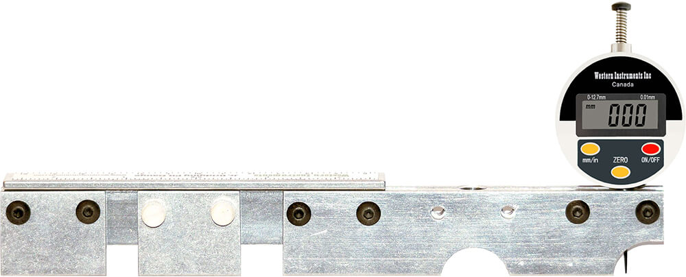
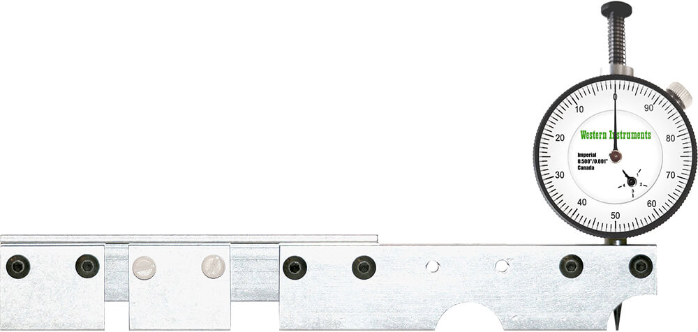
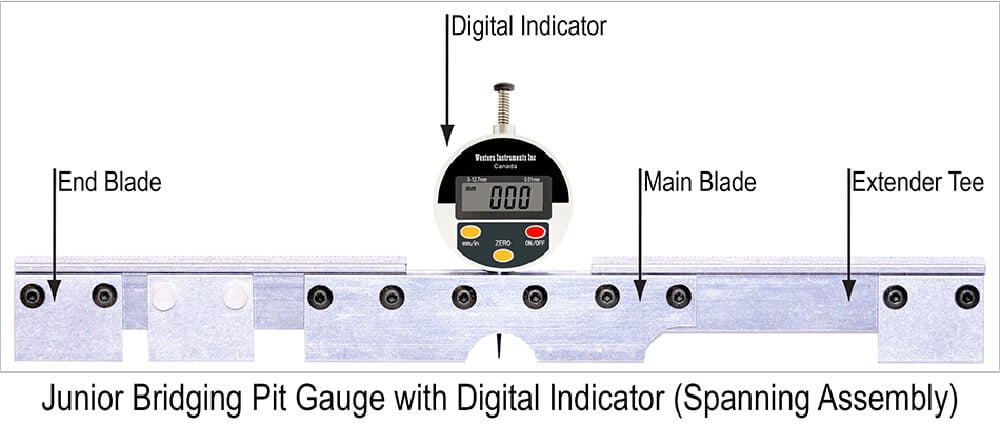
Jr. Bridging Pit Gauge® Group![]()
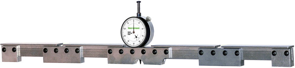
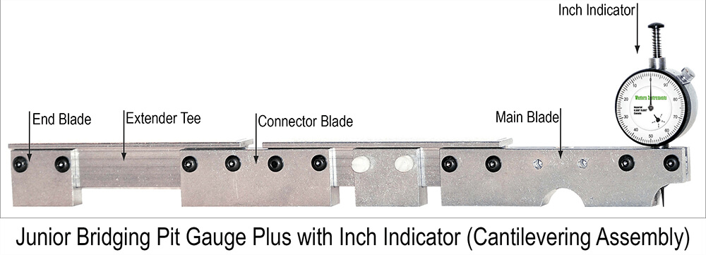
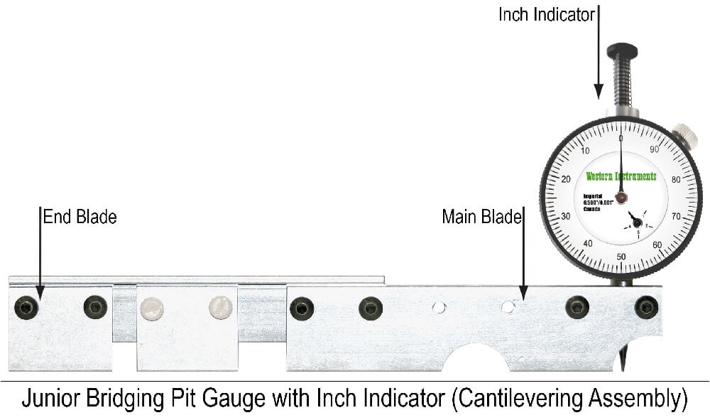
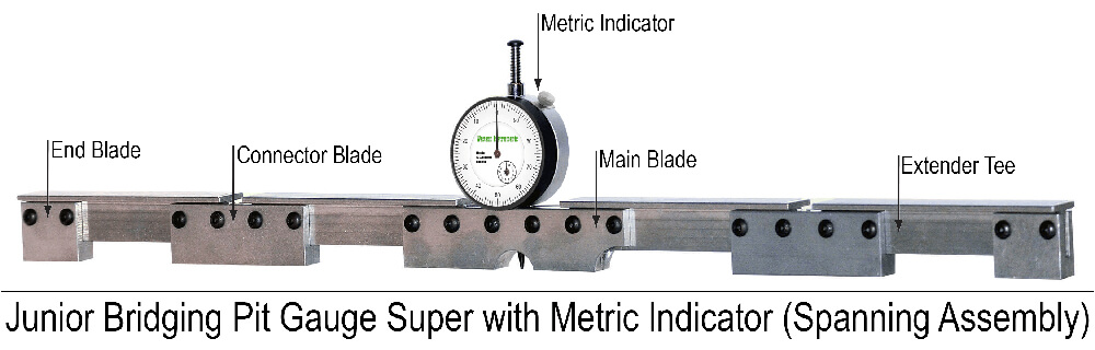
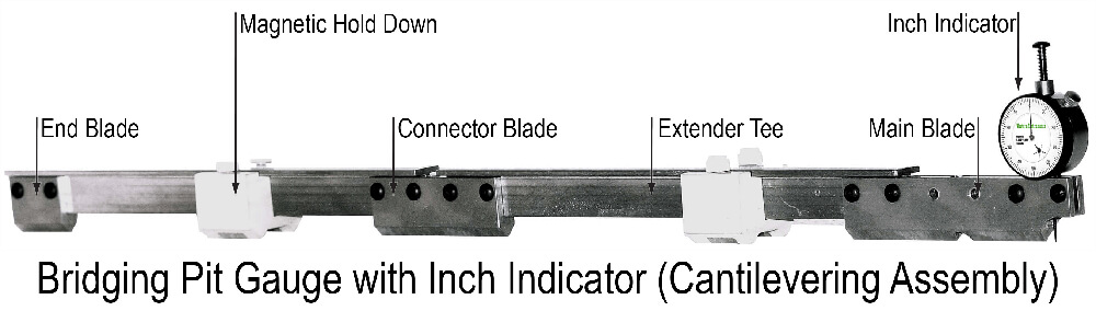
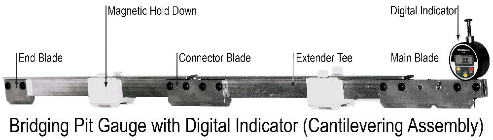
The Jr. Bridging Pit Gauge® Group provides Inspectors with an Economical Alternative to the Bridging Pit Gauge System®. The new Jr. Bridging Pit Gauge® is available as 4 models; the standard Jr. Bridging Pit Gauge®, the basic Jr. Bridging Pit Gauge®, the Plus, and the Super. The standard Jr. Bridging Pit Gauge® assembles to an overall length of 13½” (340mm). The Jr. Bridging Pit Gauge Plus® can be assembled in either Spanning or Cantilevering Configurations up to 15 ½” (394mm) long. While the Jr. Bridging Pit Gauge Super® can also be assembled in both Spanning or Cantilevering Configurations, up to 27” (685mm) long.
The Junior’s Main Blade, and the optional Extender Blades are fitted with strong magnets that secure any of the Jr. Bridging Pit Gauges® to the surface of the workpiece. These Magnetic Hold Downs have several benefits, such as; Aligning the unit to Concave or Convex surfaces, keeping the operator free to record readings or manipulate the assembly when Scanning through Pits and Weight loss Corrosion. These features position the Plus, and the Super far ahead of any competitive units.
![]()
Jr. Bridging Pit Gauge® Group - 4 Models Available![]()
 |
 |
 |
 |
| Jr. Bridging Pit Gauge® N88-11 | Jr. Bridging Pit Gauge Basic® N88-11B | Jr. Bridging Pit Gauge Plus® N88-11P | Jr. Bridging Pit Gauge Super® N88-11S |
| Description | Description | Description | Description |
| Main Blade | Main Blade | Main Blade | Main Blade |
| 2-Extender Tees | Connector Blade | Connector Blade | 3-Connector Blades |
2-End Blades |
Extender Tees |
2-Extender Tees | 4-Extender Tees |
Hardware |
End Blade |
2-End Blades | 2-End Blades |
Extra Contact Point |
Hardware |
Hardware | Hardware |
Operator Manual |
Operator Manual |
Extra Contact Point |
Extra Contact Point |
| Carrying Case | Carrying Case | Operator Manual |
Operator Manual |
| Carrying Case | Carrying Case |
![]()
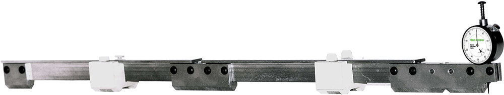
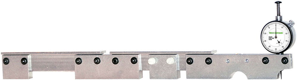
Bridging Pit Gauge® System![]()
The Bridging Pit Gauge® System allows the Corrosion Inspector to Span over or Cantilever into Large Areas of Weight Loss Corrosion, to obtain accurate and consistent measurements, or cross sections, of Pit Depth. As conditions dictate, the operator can simply use the Main Blade or can assemble the Bridging Pit Gauge® up to an over all length of 28½” (725mm).
The contact Surfaces (Blades) of the Bridging Pit Gauge® are fitted with an exclusive Knife Edge, so they can be used on Flat, ID (Convex), and OD (Concave) Surfaces, where a flat or notched contact surface can introduces error on Convex Surfaces. Like our Standard Pit Gauges, the Knife Edge gives the operator a clear view of the contact point, and the area being inspected.
With the addition of the optional Magnetic Hold Downs, the operator uses their width to quickly align the Bridging Pit Gauge System® to a curved surface. This leaves his hands free to scan through very large areas of weight loss corrosion. This holds true when the Bridge Elements have been assembled with a slight contour on an irregular surface.
![]()
Bridging Pit Gauge® System - 2 Models Available![]()
 |
 |
||
| Bridging Pit Gauge® N88-9 | Bridging Pit Gauge Basic® N88-9B | ||
| Description | Description | ||
| Main Blade | Connector Blade | 2-Extender Tees | Main Blade |
| End Blade | Slider Blade | Hardware | Operator Manual |
| Extra Contact Point | Operator Manual | Carrying Case | Carrying Case |
![]()
Bridge Type Pit Gauges - Accessories Comparison Chart![]()
| Jr. Bridging Pit Gauge® Group | Bridging Pit Gauge® System | |||||
| Name | Part # | Description | Name | Part # | Description | |
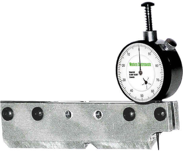
| Main Blade | N88-11-1 | Center and End Dial Indicator Mounting Positions, Fitted Permanent Magnets. Cutaway Nose for next to welds. 5.5” (144mm) long. | Main Blade | N88-9-1 | Center and End Dial Indicator Mounting Positions, Cutaway Nose for next to welds. 5.5” (144mm) long. | |
| Connector Blade | N88-11-2 | Joins Tee Sections to increase length. Fitted Permanent Magnet. 3.5“ (90mm) long. | Connector Blade | N88-9-2 | Joins Tee Sections to increase length. 3.5“ (90mm) long. | |
| End Blade | N88-11-3 | Mounts on end of Tee for extra contact. 1.5” (38mm) long. Doubles as Slider Blade for Plus® and Super® models. | End Blade | N88-9-3 | Mounts on end of Tee for extra contact. 1.5” (38mm) long. | |
| Extender Tee | N88-11-5 | Extends effective length of all models. 5.5” (140mm) long (Longer Tees are optional). | Slider Blade | N88-9-4 | Extra Point of Contact and doubles as an End Blade in Spanning Configuration. 1.5“ (38mm) long. | |
| Fastener Kit | N88-11-7 | Fasteners, Allen Key, Nylon Thumb Screws, Contact Point. | Extender Tee | N88-9-5 | Extends effective length of all models. 12” (305mm) long (Longer Tees are optional). | |
| Carrying Case | N88-11-8 | Hard Sided Plastic Carrying Case for entire kit. | Magnetic Hold Downs |
N88-9-6 | required for each Tee Section used. 15/8” (41mm) long. | |
| Fastener Kit | N88-9-7 | Fasteners, Allen Key, Nylon Thumb Screws, Contact Point. | ||||
| Carrying Case | N88-9-8 | Hard Sided Plastic Carrying Case for entire kit. | ||||
![]()
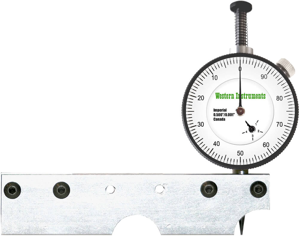
Bridge Type Pit Gauges - Features![]()
Assembly
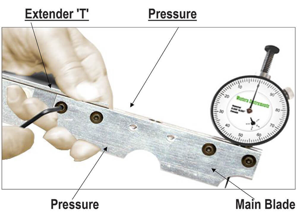
All Bridge type Blades (Main, Extender, End, & Slider) have two distinct sides, that are differentiated by the transverse mounting holes. On one side there is a clearance hole, while on the opposite side the hole is threaded (#10-24 UNC). When assembling, start the fasteners on the Thread Clearance Side of the Blades, so the fasteners can be properly tightened against the Extender Tee’s. Do not tighten fasteners if an Extender Tee is not within the Slot area of a Blade.
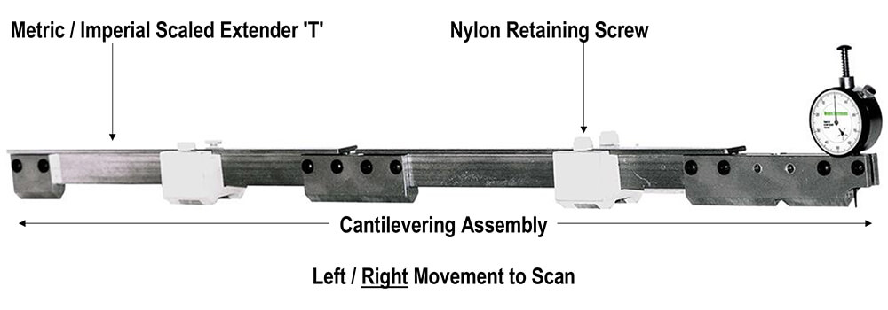
When assembling the unit, press firmly (as illustrated) on the Extender T, and the Blade you are attaching it to, while tightening the 10-24x½” Button Head Machine Screws with the 1/8” Allen Key. When assembled in this fashion, the overall length of the unit should have a straightness of approximately +/-0.015”. When more accuracy is required, assemble the unit on a flat surface.
If the surface of the workpiece has an irregular surface (slight curve, distinct bend or hills and valleys), simply assemble the Bridging Bar, but do not tighten the fasteners. This will leave the Bridge loose and free to match the contour of the workpiece. When the operator has contoured the assembled Bridge, all the fasteners can be tightened. The operator should be mindful that this contouring assembly will be fine at a given point, however it will need to be checked when the Bridging Bar is repositioned.
 |
 |
 |
 |
 |
 |
 |
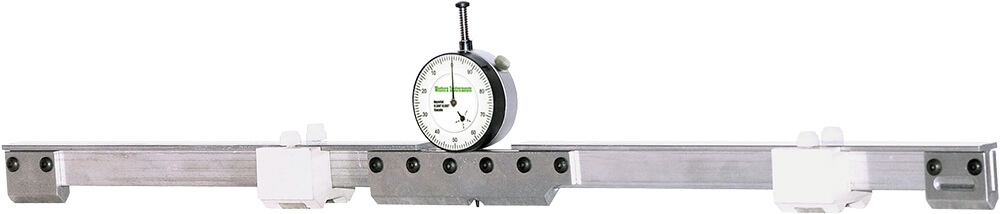
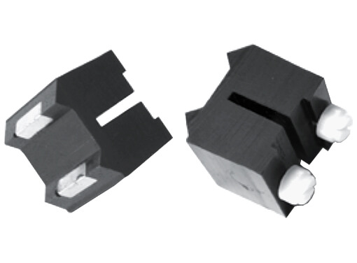
Magnetic Hold Downs
Magnetic Hold Downs are intended for Scanning with a Bridging Pit Gauge®, however they can be used on any of the Jr. Bridging Pit Gauge® Group, with a diminished range of motion. Magnetic Hold Downs also provide the inspector with increased mobility, as he is not required to support the Bridging Pit Gauge. The following are instructions for the use, and using, the Magnetic Hold Down Blocks.
Magnetic Hold Down Blocks are designed to easily slide on the Extender Tee’s, and are best put in lace prior to assembly. With the Bridge assembled, and placed on the workpiece, the entire ridging Pit Gauge® can travel over a distance of about 9” (290mm). Longitudinal or position easurements of the Bridging Pit Gauge® are taken off the Scales (imperial and metric divisions) hat are fastened to the top of the Extender Tees.
Each Magnetic Hold Down is equiped with 2 (two) 1/4"-20 UNC Nylon Thumb Screws. The Thumb Screws have two purposes, firstly to retain or capture the Magnetic Hold Down onto the Extender Tee. The second use of the Nylon Thumb Screws is to set the tension or to lock the Magnetic Hold Downs. As an example, if the Bridging Pit Gauge® is being used vertically, the operator will want the tension set higher, to keep the unit from sliding. If the Bridging Pit Gauge® is being used on a highly irregular surface, the operator will want the Nylon Thumb Screws set very loose, to allow the Blades to more easily slide over the workpiece.
When setting a Bridge to a Convex surface, such as the OD of a Pipe, or a Concave surface, such as the ID of a Vessel, the Magnetic Hold Downs are used to align the entire assembly. The operator will see this when he attempts to rock the Magnetic Hold Downs from Side to Side. If the unit rocks, the Magnetic Hold Downs are not on the same Longitudinal Axis and must be realigned. When the rocking stops, the operator knows the Bridge is aligned, however, most formed surfaces (pipe, vessels, and tanks) are irregular, so rocking may not be eliminated but must be kept to a minimum to increase measurement accuracy. When preparing for a Scan, the Magnetic Hold Downs should be placed at the correct longitudinal position along the Extender Tee. When general evaluation is being done, and the operator is not recording measurements, place the Magnetic Hold Downs in the Middle of the Tee, to allow movement of the Bridge in both directions. When the operator is going to record measurements, for Plotting a Cross-Section, place the Magnetic Hold Downs at the end position of the scan, then move the bridge to the starting position. The operator takes a reference reading, between a magnetic Hold Down and the Scale on the Tee, before starting the longitudinal movement. |
 |
Scanning
Firstly, after a Bridge is assembled, adjusted for the surface contour, and the Magnetic Hold Downs aligned to the surface, the Dial Indicator must be Zeroed (Height or Scale). This will ensure accurate and reproducible measurements. Every time the Bridge is moved to a new location, these parameters (Contour, Alignment, and Hold Down position) must be rechecked and the Dial Indicator re-Zeroed.
With the Bridge Type Pit Gauge fully assembled and placed on the workpiece, Pit Depths and Longitudinal travel can be made. This travel permits the Dial Indicator’s Contact Point to be moved along the work piece incrementally, to take multiple Pit Measurements. Longitudinal or position measurements are taken off the Scales that are fastened to the Extender Tees. The measurements (depth and length) can then be plotted to obtain a Cross-Sectional View of the corrosion profile.
Scanning through a Pit is covered earlier in this guide, but merits repeating. Western’s Dial Indicators have the special Push to Read feature, which allows the operator to Scan through a Pit to obtain an idea of the shape. By placing the index finger on the Plunger, the operator can put a slight amount of pressure onto the Contact Point. The operator then pulls the Pit Gauge Blade through the Pit, paying careful attention that the contact point does not catch on the surface. This allows the operator to watch the depth indications, so he will see both depth and length displacement. Operators should remember basic survey principles when plotting cross sections. Furthermore, if radial movements are made in increments, and recorded, an entire area of corrosion (lake type) can be mapped. |
 |


